1. Principle of the "data on the fly" - fast communication
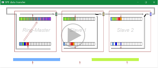
The video (10:30 min) shows how data are transferred in which time, how data can be used already in a short time after receiving, and how a fast control can work with less dead time also in distributed systems though communication.
Background: A simple controller causes two step times as dead time for a closed loop control. 1/2 step time results for measurement signals, 1/2 step time results also for the output signals. The measurement value should represent the average of the period before, as also the output value for the period after output. Additionally there is approximately 1 step time for the control itself, or exact one step time if input and output average values are in phase. This classic control may need long lines for analog signals and output signals on a width spread area. If that are replaced by digital transmission, classically it needs additional dead times because of the transmissions.
In opposite the SPE implementation with Ring communication and the "data on the fly" approach does not cause that. This allows using the 'slow' but reliable data rate of 10 MBit/s, also usable for distances till or over 1000 m in a plant. Look on the video: German: SpeDataTransfer_de.mp4
2. Usage with specific OSI Leve2 for fast communication
 This video (6 min) was created in July 2022.
In the pre-development the focus was firstly to the transmission in a 50 µs cycle
but with the 10 Mbit/s standard for long lines (1 km) and reliable signals in electrical plants.
The possibility of closing the connection to the standard network,
in particular a PC in the network, was not the main focus in this first step.
The 50 µs cycle requires definition of a special OSI 2 level data definition.
This video (6 min) was created in July 2022.
In the pre-development the focus was firstly to the transmission in a 50 µs cycle
but with the 10 Mbit/s standard for long lines (1 km) and reliable signals in electrical plants.
The possibility of closing the connection to the standard network,
in particular a PC in the network, was not the main focus in this first step.
The 50 µs cycle requires definition of a special OSI 2 level data definition.
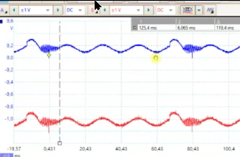
 This video (3:04 min) shows the signal play on the SPE wires, Signal transmission over 100 m, Input signals.
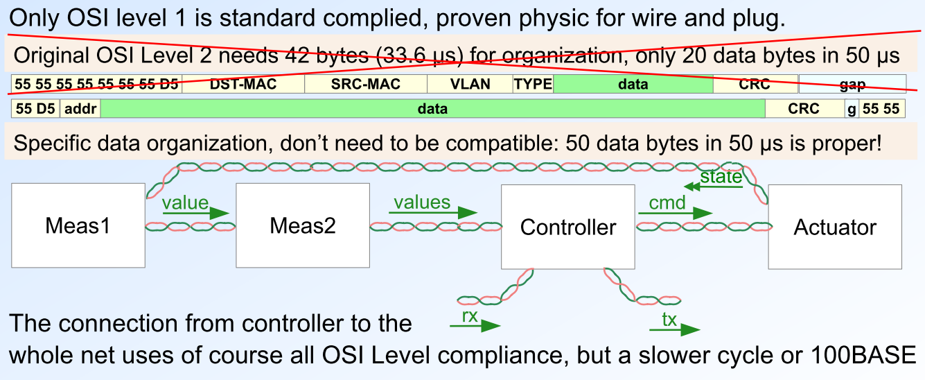 Now this video (7:20 min) shows the approach to satisfy the requirement to transmit ~ 40 user data bytes in a 50 us cycle.
The standard head bytes (OSI level 2) are removed, and also the gap.
This is possible because the stations are connected with Ring Topology (hardware dedicated addressing)
without necessity of sharing the line.
Now this video (7:20 min) shows the approach to satisfy the requirement to transmit ~ 40 user data bytes in a 50 us cycle.
The standard head bytes (OSI level 2) are removed, and also the gap.
This is possible because the stations are connected with Ring Topology (hardware dedicated addressing)
without necessity of sharing the line.
But this approach is not compatible with a standard ethernet routing. It means it is the specific solution for fast data transfer between dedicated stations.
3. Usage with standard communication PC in ring / as receiver
This SPE solution may be also interesting and it is proper for a longer cycle, for example 1 ms. In this longer cycle a standard telegram can be transmitted and received, which is also connected immediately to a PC. It means it is the solution for both, fast synchronized communication in a plant, and offer the communication data to a PC network to evaluate it.
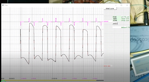
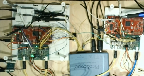 The first video (2:58 min), in german: ../../videos/Hw_Aufbau_PCimRing_de.mp4 shows the hardware assembly and some signals on scope.
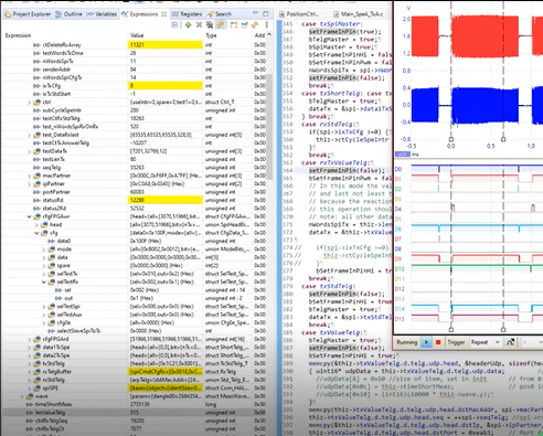
 This video (11:44 min), in german: ../../videos/ApplMechanCtrl_Gui_de.mp4
shows a Graphical User Interface (GUI) running on PC (in Java) which evaluates immediately the incoming data.
The GUI itself is a standard solution.
It is configured per textual scripts for the graphical appearance and also to select the hardware signals.
This video (11:44 min), in german: ../../videos/ApplMechanCtrl_Gui_de.mp4
shows a Graphical User Interface (GUI) running on PC (in Java) which evaluates immediately the incoming data.
The GUI itself is a standard solution.
It is configured per textual scripts for the graphical appearance and also to select the hardware signals.
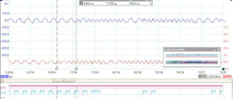
 This video (7:08 min), in german: ../../videos/TestSignals_FPGA_1msTelg_de.mp4
shows some signals on the scope to explain signals from FPGA and on the SPE lines.
This video (7:08 min), in german: ../../videos/TestSignals_FPGA_1msTelg_de.mp4
shows some signals on the scope to explain signals from FPGA and on the SPE lines.
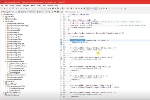 The last not least video (12:55 min), in german: ../../videos/Java_eWay_de.mp4
shows how Java is used for a script controlable evaluation
with only some individual plugin classes inside the given standard GUI application for signal evaluation.
The last not least video (12:55 min), in german: ../../videos/Java_eWay_de.mp4
shows how Java is used for a script controlable evaluation
with only some individual plugin classes inside the given standard GUI application for signal evaluation.
-
more videos will be following for further experience.