Version 2026-04-18
This file contains some links and some videos for OFB usage in LibreOffice graphic programming, code generation for C(++) and test
FBcl means 'Function Block Connection Language' which is the textual description of the graphic. The idea comes from ~2018.
OFB means 'Object oriented Function Block graphic' with basic experience in the beginning of the 2000th, a presentation on ESE congress in 2017 (article https://www.embedded-software-engineering.de/grafische-objektorientierte-c-programmierung-mit-simulink-a-726729/).
Graphical programming of function blocks has been common practice for decades. The automation control, for example Simatic-S7 or Codesys, use it with its "FBD" language (Function Block Diagrams). Another representative is Simulink © Mathworks. There are some more similar tools for that. But for these Function Block programming solutions ObjectOrientation is missing. It is also non-conform to UML. The OFB closes this missing relation with some enhancements in concept, using of Aggregations (UML like), and also an event control system for execution.
What is the approach? Drawing the software with graphic and code generation in C/++ (maybe later also in Rust, or in Java, also VHDL for FPGA may be in focus). so that the functionality is seen and understandable by everybody with physic knowledge, obviously, no code lines. But the code lines are generated and follows guaranteed the graphic. Graphical software development does not save effort (money) for development. It improves the documentation! That’s the benefit. The basis for the graphics should be an available, proven tool (without basic costs, usable by anyone at any time). LibreOffice was chosen for this purpose. It is well-known and easy to use for this approach of graphics. The translation is an algorithm written in Java, which reads the graphic data and have capabilities for Code generation.
1. Resources, hints for download and work
CapabilitiesConceptsOFB-2026-03-22.pdf contains a brief overview (15 pages) of all functionalities.
(previous: CapabilitiesConceptsOFB-2026-03-12.pdf)
The full documentation is yet partially in progress, see chapter Documentation
You can write feedbacks and questions to info (at) vishia.org
1.1. Download zip and install the tools
Some examples and the load_tools are contained in the following zip file:
-
https://vishia.org/fbg/deploy/OFB_Presentation-2026-04-19.zip: Last version, even Linux tested
-
Download and extract the zip file to any proper directory on your PC. Then all files are stored beneath
OFB_Presentation-2026-04-19in your destination directory. Use this to work, or copy the content to a new created directoryOFB_Presentation…beside again, as your working area to have the capability to compare with the original.
 Any_Location_On_Harddisk
  +-- OFB_presentation-2026-04-19.zip    downloaded zipfile
  +-- OFB_presentation-2026-04-19        unpacked content here
  +-- OFB_presentation_MyTests           possible copy to work in it.
-
The directory tree beneath
OFB_Presentationhave a designated structure which is presented in Hints Handling load, file tree and detailed explained in ../../SwEng/html/srcFileTree.html -
Note that '~~/path/to/file' means with ~~: ~~ is the working dir, e.g.
OFB_presentation_MyTestswhereby the simple ~ is the placeholder for definitely things in the context. -
Install the tools. The tools are simple jar files running on Java in version 8 or higher. Installing the tools should be done under MS-Windows with execution of the batch file:
~~/tools/+loadAndCheckTools-vishiaOFB.batand adequate for Linux
~.sh. This batch file or shell script calls as Java process a loader (vishiaGetWebfile-2025-12-21.jar) from the given internet location on this web page with a given and compared check sum (MD5) contained in the filetools_vishiaOFB.bomorvishiaOFB_tools.bombeside. The 'bom' is a 'software bill of material' as known also in other presentations and discussions. This ensures even the security test.
If the tools (jar files) are already contained in the tools folder, this scripts checks and shows the correctness.
1.2. Just have a short look into the examples and files
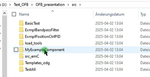
The zip file contains some examples, which are also shown in the videos below. You find the LibreOffice draw files in certain directories:
-
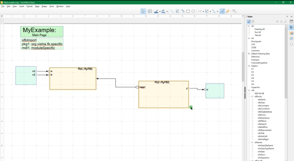
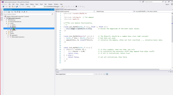
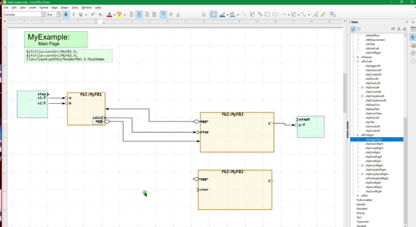
~~/src/+MyExampleComponent/odg/MyExample.odg: This is a basically example showing the principle of using the graphic. Here especially manual written codes in C are included in the graphical module, and the principle of aggregations are demonstrated. -
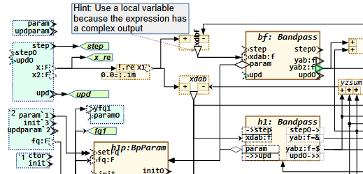
~~/src/+ExmplBandpassFilter/odg/OrthBandpassFilter.odg: elaborately example but with only one graphic level module. It organizes filters for 50 Hz grid frequency drop detection and filter harmonics. -
~~/src/+ExmplPositionCtrlPID/odg/ExmplPositionCtrlPID.odg: an example showing the capability of working with non deterministic data types. It uses more module levels in graphic. -
~~/src/+StatePosCtrl/odg/StatePosCtrl.odg: an example using parts fromExmplPositionCtrlPIDas used module. It contains a state machine for fast reaction. -
~~/src/+BasicTest/odg/BasicTest.odg: It is a hodgepodge of some examples showing basic capabilities used as test. -
~~/src/+StateM_Test/odg/StateM.odg: Also a hodgepodge but for state machine capability. -
~~/src/Templates_OFB/odg/OFB_DiagramTemplate.odg: Graphic file as template with the styles and shapes. The styles should be always taken from here. -
~~/src/LibOFB_emC/odg/LibCtrl_emC.odg: 'Library' file with definition of modules as FBtype which are contained in -
~~/src/src_emC/cpp/emC: some sources in C and C++ language which comes from the emC-concept (../../emc/index.html) used in the examples. -
~~/src/scripts/*: This directory contains some scripts used for translation and test.
The different directories below src are the Component's directories.
A Component is one part with all its Graphic files, control files, generated target source
and report files. Note that the examples starts all with + as first character of the directory name,
to get better overview.
What about the script files on root? They help to create a so named linked directory for build
into the TMP directory, ready to use on demand if desired here. See chapter Translate the example from graphic into target C/++ code.
Notes for the version 2026-04-18:
-
Some capabilities for state machines should be improved, planned also for the next time.
1.3. Documentation
-
https://vishia.org/fbg/pdf/CapabilitiesConceptsOFB-2026-03-22.pdf contains a brief overview (15 pages) of all functionalities.
-
https://vishia.org/fbg/pdf/Handling-OFB_VishiaDiagrams-2025-07-23.pdf The current manual for handling with OFB. (Of course meanwhile it’s November and the docu is improved, but unfortunately yet not offered here. In a few days it’s Christmas .- oh it’s already spring coming)
Note: Use two-page view if you have a larger monitor (1980 x 1020 or more). The documentation is page-oriented. The odd page should be on right side ('book view'), but because usual the Browser-pdf view don’t support the book view an empty left page is introduced for that.
-
https://vishia.org/fbg/pdf/Handling-OFB_VishiaDiagrams-Bookmode.pdf The same current manual for handling with OFB but reading in book mode (title odd page right).
-
https://vishia.org/fbg/pdf/Impl-OFB_VishiaDiagrams-2024-11-01.pdf - how does it work, internals It is currently not actual.
-
https://vishia.org/fbg/pdf/OFB-Examples.odg-Ccode-2025-03-12a.pdf This is the paper shown on Embedded World 2025
What is the approach
-
Graphical programming for embedded control is not the way to save money (this is not true also by using other tools), it is the way to get a good correct and understandable documentation for the software.
-
That’s whay it is important to generate target code for the embedded controller from the graphic.
-
Usual Function Block Diagrams are used for such approaches, this is also done here.
-
But the UML (Unified Modelling Language) plays an important role for software architecture and also software understandment. That’s why a way is searchted, and found, to combine capabilities of UML with Function Block graphic. It is possible that this opens a proper way to go to a joining of UML with Function Block graphic. For that it is named OFB Object oriented Function Block graphic.
-
One of the important idea is: Use the capability from the Free Open Source tool LibreOffice draw to draw the graphic. And in fact, all necessities are supported.
-
The here offered tool is the translator from a LibreOffice draw file (
*.odg) to the target code yet in C/++ language. -
There are a lot of details, possibilities of the graphic, handling, translation parameters etc. explained in the docu.
1.4. Translate the example from graphic into target C/++ code
If you want to test what’s happen while translation, before or after reading the docu, go with any File Explorer to one directory of the examples, (a component), and then to
~~/src/ExmplPositionCtrlPID/makeScripts/genSrc_odg.bat
Start this batch or on Linux the adequate genSrc_odg.sh script.
This reads the graphic, translates the content and writes the result to
~~/build/ExmplPositionCtrlPID/
If this works, the tools are proper installed.
But wait a moment, what is build:
General, sources are stored in ~~/src, results, also the generated sources from graphic
should not be merged with the first intrinsic sources.
That is why ~~/build should be the target of all translations.
But see next chapter, in a second step the new built sources are copied as "sources to use for compilation"
into ~~/src/$CMPN/cpp/gensrc.
In ~~/build/$CMPN/cpp/report also some really temporary outputs are stored,
which are only interesting if some thing is wrong.
Because of really temporaries, it can be seen as recommended,
that this build directory should be a symbolic link which refers either to a RAM disk.
This is ideal to save stress for a SSD drive, and has also faster access. Today’s PCs have enough RAM.
Details explanations see chapter on end of this site: Write results to build, optimising access to the hard disk, RAMdisk and symbolic links
To redirect the build directory to another destination symbolic links can be used, which are JUNCTIONs in Windows.
To organise that, batch or shell scripts are arranged beside src and build:
~~/+mklink_build_TMP.bat
~~/+mklink_build_RAMD.sh
1.5. Compare newly generated sources with the versions before
Are the sources proper generated after changes in the graphic? Which is changed in the sources? Is somewhat by accident destroyed in the graphic, a dangling connection, a removed pins or such?
That are important questions. If you write source code, usual a source repository (git) is used to monitor all changes. If per accident a part of software is bad, it can be fast detected by comparison of the source with the version before.
In graphic programming, faulty changes per accident are more probable and maybe worse to detect.
That’s why a textual different view of the generated sources (and also some report files) can help to see the truth what’s happen.
A secondary consideration: The generated target sources should not be seen as black box (as some other graphic tools imply). The hard work to manage embedded software are the real text sources. Graphical programming first helps to understand the code. Source code generation is not primary done to hide the sources, or to save time and money for code writing, it is done to guarantee that the graphic and the sources are identically. Which is usual not true if the graphic is only drawn as documentation afterwards.
Hence, you should look into the sources, knwo the source code principles etc.
Thats why a "diff view" is recommended or necessary.
There are some different diff tools available. Here using Winmerge is preferred. https://winmerge.org/.
It is very proper for the approach.
Use the winmerge-2.16.50-exe.zip to download.
It is a 32-bit Windows version as 'portable' or just 'copy deployment'.
It runs also with Linux using wine.
It is recommended to install Winmerge not in the Program Files folder, that is for Windows stuff,
use instead in extra C:\Programs folder for your own additional tools.
To call the Winmerge or also another diff tool, the following bat or sh in the scripts are used:
~~/src/scripts/WindowsEnv/fdiff.bat
~~/src/scripts/LinuxEnv/fdiff.sh
After installing Winmerge you need to adapt this script(s). The default choice for the Winmerge path there is:
C:\Programs\WinMerge\WinMergeU.exe
If Winmerge is installed and this file is correct, then after code generation Winmerge is started to compare the folders:
~~/build/$CMPN/cpp/gensrc <==> ~~/src/$CMPN/cpp/gensrc
With simple textual comparison, decision that the new generated sources are correct and copy with quick push over using <Alt-arrow right> you can fast synchronise this files. Have it compared, store the last used version.
What is the meaning of all these generated files - look in the documentation.
1.6. Compile the examples for a Linux or Windows-Environment and run/test it
One generally approach of development in C/++ language should be:
Sources in C or C++ should be able to compile and test in any environment,
on embedded hardware and without modifications or sophisticated compiler switches (''#ifdef'')
even on PC platforms, to test the algorithm.
This is of course not true for the pure hardware level, working with input and output ports,
specific hardware on embedded control etc.
But it is appropriate for the growth of software, for the algorithm itself.
Hardware premises can be evaluated.
That’s the taks of a so named HAL (Hardware Adaption Layer).
Instead output to a port a specific (global) variable can be visited and output via printf
or better in a curve view presentation.
The interrupts can be evaluated by a while loop in a main program.
That are all known approaches.
It is also often claimed that developers need to specialize in either embedded hardware or PC applications.
This narrative is false if PC compilation is done with the goal of simulate the embedded hardware.
The examples presents partially controller algorithm. For that it is interesting to see the behavior in a simulation environment on PC looking the results is graphical curves.
This objective is achieved by supplementing the translated sources from OFB with a main environment
for cyclically execution in a main-loop.
You find this manual written C sources in ~~/src/EXAMPLE/cpp/testEnv.
To compile and execute it there are some possibilities of IDEs, and a Curve view application for showing the results.
Working with that needs the installation of the compiler tools and at least one IDE. There are some possibilities.
1.6.1. Codeblocks as IDE-tool - the possible beginners approach
IDE is the 'Integrated Development Environment' to compile and test/debug and also search cross references in the sources.
For beginners there is a simple start level: Using Codeblocks:
It may be seen as recommended using the codeblocks-25.03mingw-nosetup.zip.
It can be unzipped and it is outside the Windows software administration, it’s for your own.
For the same reason it is recommended storing codeblocks in
C:\Programs\Codeblocks\2025\*
instead in C:\Program Files. Use the last one only for software administrated by the operation system.
This Codeblocks zip archieve contains a complete 'MinGW' environment, which offers the gcc compiler suite also for free usage, see Compile per command line to get an executable to run
For Linux and also Mac it is similar. The gcc suite should be installed by the known installer packages for the adequate Linux distribution. CodeBlocks can be installed by downloading the adequate rpm or deb packages from the www.codeblocks.org download side.
1.6.2. Codeblocks projects in the example
You find the copy of the codeblock project for each example in
~~/src/EXAMPLE/IDE_CB_Windows/PROJECT.cbp and also adequate for Linux
~~/src/EXAMPLE/IDE_CB_Linux (...Windows)
 +-- PROJECT.cbp               The code blocks project itself
 +-- +clean_mkLink_build.sh    ...bat a script to organize build outputs
 +-- +spawn_IDE_CB_Linux.bat   ...Windows.bat to spawn it.
The spawn is a short script which copies the files from this location to an IDE folder
beside src.
~~
 +-- tools ...
 +-- src ...
 +-- IDE
      +-- EXAMPLE
           +-- IDE_CB_Windows   (...Linux)
                +-- bin
                +-- obj
                +-- PROJECT.cbp
                +-- +clean_mkLink_build.sh    ...bat
The idea of this approach is: strict separation of generated stuff ('artifacts')
from real sources.
The artifacts, the object files, the executable and some elaborately intermediate files
needs Megabytes on storage on disk and they are all reproducible on demand with less time effort
(some seconds).
The only one real source in this IDE folder is the codeblocks project itself (.cbp).
This is the same situation also for Visual Studio.
For Microsoft Visual Studio there are three project files
(.sln, .vcprj and .vcprj.filters).
All other files are artifacts, especially the elaborately ``.VC.db'' file.
The project file is only rarely changed.
If this is done (save the project after changes) either the original file is automatically even updated.
This is true if this remains a non broken 'hard link'.
But sometimes the hard linked relation is broken. Then you should only compare and copy this project file
(the three project files for MS Visual Studio) to the original on ~~/src/EXAMPLE/IDE….
Information: A hard linked file is only one file on your hard disk, which is referred by more as one directory entries. This is a concept given also on old UNIX systems, any time available on Linux, and introduced in Windows beginning with Windows-XP, but rarely documented. It is supported by MS Visual Studio and also Codeblocks, but often ordinary text editors break the hard link. Because there working approach were designed in times of DOS and older Windows versions. Hard links were not broken on working approaches for files: open - read - modify/write - close. But text editors works often in the working approach open - read - close and later open - write (create new) - close. This creates a new file, non related to the original and hence breaks the hard link.
1.6.3. Visual Studio support
All examples have a Visual Studio projects given to compile and run the examples in Windows.
You find the copy of this project for each example in ~~/src/EXAMPLE/IDE_MSC.
Also (especially) for Visual Studio the spawn approach is also recommended
as described above for Codeblocks for the same reasons: separation of sources and artifacts,
prevent Megabyte of artifact files (.db, Object files) inside the sources merged.
1.6.4. Compile per command line to get an executable to run
The idea for that is: Focus your work to the graphical models. Prepare the simulation environment (main.c, IDE) only one time. Do not focus on C/++, instead focus on the graphic. Work with one button approach: Press the button [OFBwNodiff] in LibreOffice, and look for the executable (simulation) results in the Curve View Scope view. Change the graphic, run and look to Curve View again etc. It means, focus your work to algorithm in graphic, not to C/++ compilation.
But the work of compilation should be done nevertheless - in background. Generally for that a make system is necessary. This make system is given here with the so named Zmake approach (see https://vishia.org/JZtxtcmd/html/Zmake.html). You can also establish Cmake or similar approaches for your own. But Zmake is proper usable. See the main chapter Details to tools and handling for further explanation
The execution of this compilation is organized in the general used OFB translation script which is also invoked from the LibreOffice macro and button. See chapter Translate the example from graphic into target C/++ code Usual the translation is started with
src\EXAMPLE\makescripts\genSrc_odg.bat``
The script calls the more complex common organization script in
src\scripts\genOFB\genSrc_odg.bat
In this script, on end, the argument (environment variable) MAKE is asked.
It it is set, then
%CMPNDIR%\makeScripts\%TARGET%.Zmake.jzTc.bat
is called, which invokes %CMPNDIR%\makeScripts/%TARGET%.Zmake.jzTc.sh
via scripts\WindowsEnv\shell.bat.
Alternatively %TARGET%.Zmake.jzTc.bat can be called also immediately by double click in Explorer
or in any other command line environment.
Adequate it is done for Linux. But Linux has shell and gcc native.
The called translation script can invoke any other make system than Zmake, organized by your own.
How Zmake works, see main chapter for Details to tools and handling.
1.6.5. Curve View
To see how does the compiled target code on PC work, a graphic output (Java program) is contained
beneath ~~/src/$CMPN/curveView
The control file for this curveview is also a result of the code generation.
The curveView communicates with the running compiled application (original given in graphic) via Socket communication.
The socket communication is programmed for each example in the main loop after each step.
The Operation system Adaption Layer in ~~/src/src_emC/cpp/emC_srcOSALspec
for Linux and Windows (which have different driver interfaces) adapts to the OS-specific socket driver.
It means socket communication from user level C/++ is not too complicated with the given support,
inclusively such things as big/little endian. It is programmed ready to use.

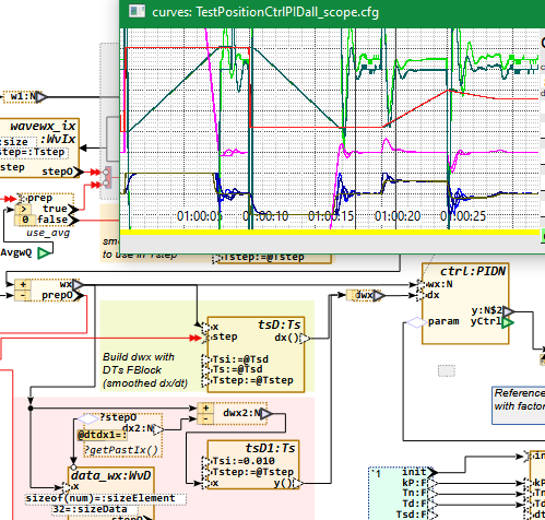
The question which signal are presented is clarified in the graphic.
See image rigth. Because of the type name beginning with TEST it is not part of the ordinary sources.
Even for this reason and beginning the FBlock name with scope it is considerated
in a specific target code generation script: src/LibOFB_emC/makeScripts/scopeEthernetComm.otx
or another similar one, select by the PCsim.args file on translation.
This script generates c and header file to feed socket communication,
see files ending with _scope.c and _scope.h in the src/$CMPN/cpp/genSrc folder.
Even src/$CMPN/cpp/genSrc/MODULE_scope.cfg will be generated,
which is used by the CurveView application for scaling and presenting.
View this *.otx file as first candidate to see how code generation is controlled.
In the image right the IP address and the ports are determined.
This should match with the used port as calling argument of the java invocation for the CurveView.
It is set to the environment variable IP_DST in the start
script src/$CMPN/curveView/CurveViewAppl.bat and …sh.
DST or destination is related to the connection from the code generated application
to the CurveView as destination, it’s related to the ip_dst argument in the graphic.
The port to send back acknowledge is given by the sender address from the source, it is ip_own in the graphic.
It means it doesn’t need to parameterise for the CurveView.
The communication is always initiated from the target application. The Curve View is listener of the UDP connection. For correct operation the CurveView should respond any received telegram to avoid data losses. The application waits in the socket communication for response with timeout. That’s why the application works slowly if the CurveView is not started.
1.7. Compile your own work for embedded control with target compiler
If you are familiar with the concept, you can start with own examples designed with OFB, translated and used with some specific C/++ sources for a target hardware. Target hardware is widely supported for example by evaluation boards, and cross-platform IDEs. You may have experience already for development in C/++ for that.
It is recommended following some considerations mentioned in the 'embedded multiplatform C/++' articles able to found in https://vishia.org/emc. But this is optional, recommended but not presumed for your work.
A part of the emC sources are placed in the OFB_presentation example zip file. The whole software archive is linked in the https://vishia.org/emc pages, especially the sources are hosted in https://github.com/JzHartmut/src_emC. It is possible or even expectable that these concepts are helpful even for your own embedded control development.
For the live cycle of an application follow the explanation in the OFB-documentation chapter 5.12 Drawing and Source code generation rules, and especially 5.12.2 Life cycle of programs in embedded control: ctor, init, step and update.
1.8. testAll, translate all examples from graphic to C code
To start a test whether all graphic files can be translated, do it, translate all the graphical source files by execution of
~~/src/TestAll/makeScripts/testAll.bat
1.9. older zip files to download
Development of such an elaborately tool and concept needs time and experience. The development has started in 2023. Comparison with older versions shows progress. Even if you have started with an older version, for comparison, they are available here:
-
https://vishia.org/fbg/deploy/OFB_presentation-2025-07-25.zip: Last version,
SHA-256 check sum: 5b654b77a82fb22077740f1ff5ce2dcd5beee5c022fb23dce372721214687d9f
MD5 check sum: 22cd4faf96765a6af308e8bd499343d8 -
https://vishia.org/fbg/deploy/OFB_presentation-2025-04-02.zip: Old version to compare it
-
https://vishia.org/fbg/deploy/UFBgl_presentation-2024-05-02.zip: Very Old version to compare it
1.10. source repositories, Gitlab
New created on 2025-March-27: Git repository on Gitlab. (The repository itself is grown since 2019):
-
https://gitlab.com/jzhartmut/OFB_Presentation content, sources in the download zip file
-
https://gitlab.com/jzhartmut/srcJava_vishiaFBcl sources for the OFB converter
-
https://gitlab.com/jzhartmut/srcJava_vishiaBase basic sources, no more is used outside the standard JRE-8
1.11. Javadoc for sources
Javadoc html of the converting tool
2. New capabilities in the version 2026-04
The new version should anyway be completed with the state machine capability, working on.
But also quests of handling a system with more modules are in focus.
2.1. Aggregation using in OFB diagrams
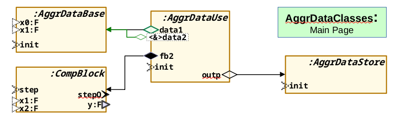
This video (13 min) shows how aggregations are used.
2.2. State Machine design shown on an example collision detection for position control
State Machines are now a substantial part of the OFB concept.
For using in embedded control it is important that State Machines does not only act for the whole system, in slower threads of a RealTime OS as often seen in large UML solutions. Instead they should act in the fastest interrupt (as often manual programmed in C/++) but in coordination with slower threads for UI (User Interface, Operation and Monitoring) handling. That was one of the goal to develop State Machine using in OFB.
3. The version 2025-07-25:
The new version comes in comparison to the April version with a lot of new features. As the versions in 2024, the April version may seen only as start.
-
https://vishia.org/fbg/deploy/OFB_presentation-2025-07-25.zip: Last version,
SHA-256 check sum: 5b654b77a82fb22077740f1ff5ce2dcd5beee5c022fb23dce372721214687d9f
MD5 check sum: 22cd4faf96765a6af308e8bd499343d8
3.1. Changes since 2025-April
Some important news are:
-
The access to data with operations and return values are now supported. The older versions were oriented, as usual also in ordinary C programming, only to (public) data. Working with operations and hence encapsulate data are a proper decision.
inlineoperations also in C language does not enforce additional calculation time on machine level. Also usage of reference variables for return values is possible. What is not clarified: Return of a reference is intrinsically an association in UML thinking, and should be handled in exact that way. Function block graphics do not deal with references, only with data flow. But usage of references is usual in C/++ programming. This should be basically proper clarified for the Object Oriented Function Block (OFB) concept. -
In opposite to this feature, also public access to structured data works, sometimes necessary for embedded applications. Inner variables well structured can be declared as outputs to immediately access from outside.
-
Defining and usage of module input and output pins is improved (as result of the changes above).
-
Usage of non determined types are supported. This is sometimes necessary if a library module is written first independent of usage in a
floatorintenvironment. The graphic is the same. The usage and code generation decides about the numeric, with unchanged graphic. -
The fix point arithmetic is improved and tested, with automatic conversion from and to float with dedicated given 'number of fractional bits'. Also using saturation arithmetic is supported. It is not yet tested elaborately in embedded hardware, but the system for that is established.
-
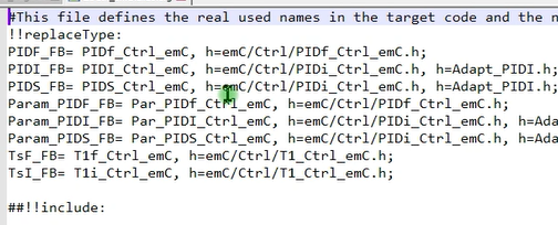
The concept of predefined FBlocks and the alias are improved. The name of a
structin C language is determined only on code generation, not already in the graphic diagrams. The mapping is done with an extra text file (-cfg:), see video below. Used names in the graphic diagrams are more independent of target implementation stuff. -
logs and comments are improved to see how and why the code is generated in the given result.
-
The translation from the graphic to target code can now be started also from LibreOffice in the toolbar, using a macro in LibreOffice, which calls the used batch file (or todo: shell script for Linux). See video below. Also executing the target code build process and start execution can be done in this kind, but is not done yet. This would be a faster way from the graphic to execution results.
All in all, some tests on living examples are done, a lot of fine tuning was done. A list of details of changes can be seen in the version history: https://gitlab.com/jzhartmut/srcJava_vishiaFBcl. Of course the documentation is improved step by step.
3.2. Videos showing the new features and working with OFB
There are some videos showing the new features and showing how working with OFB. The video is linked by clicking on the image on the right. It is an mp4 file hosted on my website.
3.2.1. Working with alias and determine the struct names in target code
This video (18 min) shows how alias designations are used and how the header files are determined from the graphic content.
It includes also the explanation how the graphic definition of FBlocks is related to the given (legacy) target code.
3.2.2. Module output possibilities, return by value, value reference variables, operation access
This video (26 min) shows possibilities of the outputs of the module as also as called function blocks also written in target language.
Operation access is the recommended style for encapsulated Object oriented programming. But beside this, for embedded C, as usual, also the public access also to structured data is supportet.
The video discusses also the possibility to use pointer access. But this is a question of associations (UML thinking), and some questions are open regarding code style, public access, const access. Associations are not yet ready to use handled in the version 2025-07, should be added in the next time. Then this video is still valid, and a second video using associations will be offered in parallel.
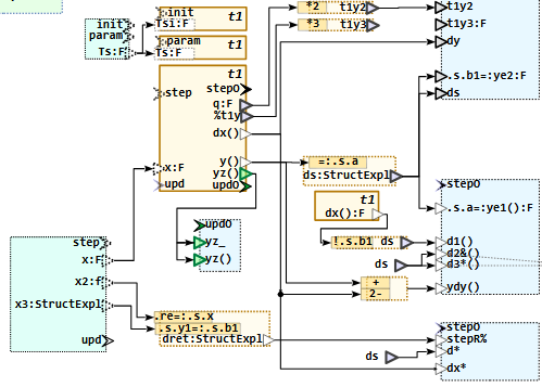
3.2.3. PID control - with different numeric data types
This video (9 min) gives a short overview with the example ''Position control with PID'' which is implemented with float,
int32 and int16 arithmetic.
It shows more details about controlling effects, especially the D-Part in PID controlling,
than details of the OFB concept.
But may be interesting as application example.
This video (21 min) shows the example ''Position control with PID'' which is implemented with float,
int32 and int16 arithmetic.
It shows more details about controlling effects, especially the D-Part in PID controlling,
than details of the OFB concept.
But may be interesting as application example.
This second video (11 min) for the same diagrams now shows, how the numeric data types are selected in code generation and from the given (legacy) core C codes.
3.2.4. Integer and saturation arithmetic, using fractional bits
This video (26 min) shows how integer artithmetic with dedicated number of fractional bits is used beside float arithmetic, with automatic conversion between, and especially how saturation for integer arithmetic is possible and works. Hint: The video has some technical hanging effects especially on end. It should be replaced by a new version.
3.2.5. How insert an icon and macro in LibreOffice draw for the translation
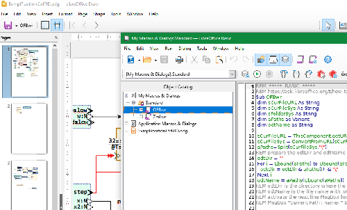
This video (8 min) shows how to insert a macro in the LibreOffice toolbar to fast start the OFB translation from LibreOffice (after saving the file).
The translation itself is controlled by a batch file (TODO offer also a shell script for linux) from the stored file.odg content. The macro does the same as start the batch file from outside. But it is faster to handle.
3.2.6. Fix a problem with hanging socket on CurveView
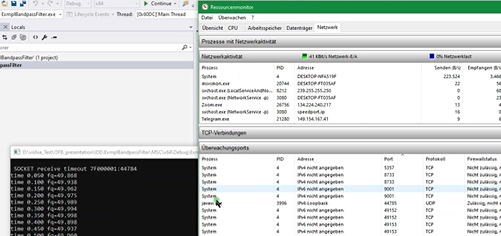
Not all is perfect. The current version of the CurveViewApplication has the problem that sometimes (rarely) it is not correct closed, and the used socket remains open. This problem should be fixed in the CurveViewAppl, which is only used here as helper. But it is not fixed yet in the moment. If it occurs, "a new boot is good", booting the PC helps. But to fix the problem also only the hanging process can be killed, using the TaskManager (of Windows). This video (8 min) shows the problem, and show how to find the blocked socket in the ResourceMonitor on Windows and kill the process. The process-ID is written to the socket in the Resource Monitor. But it is unfortunately not written in the standard view of the task manager, only in the "Details" view on the task manager.
4. Presentation on Linux-Day in Augsburg, Germany
My presentation in German language has shown the OFB-Converter only as example how to use indirect styles in documentation and graphic. The topic there was LibreOffice, not the OFB-Converter. But nevertheless the presentation may show some hints on usage also for the OFB topic:
https://youtu.be/CfxPV5skklM The presentation itself, German.
5. Version 2025-04-02:
Hint: The videos below are also valid for the current version, only small changes in implementation are different. The approach and system is not generally changed.
Many details are improved in the last year, in the work is also current in progress. But new versions has run also in the past with changed versions. The base is stable.
My own main focus should now be on improving the comprehensibility of the sources (programmed in Java) All tagged or downloadable versions are (and should be in the future) tested and fulfill the examples shown. The second effort should go into the documentation. The state machines are not yet available, but are in progress. Follow the videos. They show what is available.
5.1. Unpack zip file, use code generation
This video right side on the image shows how to unpack and start test with the new zip file from 2025-april-02. It is a short presentation, 6min with ~43 MByte
5.2. Detail explanation with example BandpassFilter
This video (in German language) right side on the image is an introduction to the new zip file from 2025-april-02. It is a longer presentation, 1h10min. The resolution is reduced (to save a little bit our world), it uses only ~200 MByte space on the server and for traffic.
6. Older content from ~2024
Older zip file to download:
-
https://vishia.org/fbg/deploy/UFBgl_presentation-2024-05-02.zip (older version from last year 2024)
The following videos are the old ones, still valid exclusive small details. They will be replaced step by step by videos with the newer versions if necessary.
A documentation can be viewed or downloaded, see start of this page.
Older and not complete documentation:
-
https://vishia.org/fbg/pdf/Impl-OFB_VishiaDiagrams-2024-11-01.pdf - how does it work, internals
-
https://vishia.org/fbg/pdf/UFBgl-Diagrams-OpenLibreoffice-2024-05-02.pdf (this was the version one year ago)
6.1. First example from 2024, goal of graphic in Libre/Open office
This first video (12 min) shows how to copy and use the template in LibreOffice for a first simple own UFBgl-diagram. It shows the general approach drawing UFBgl diagrams.
This second video (16 min) shows the code generation for this first example,
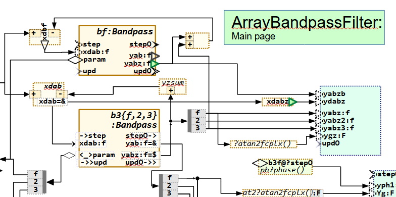
6.2. Comprehensive example: Bandpass Filter for 50 Hz electrical grid
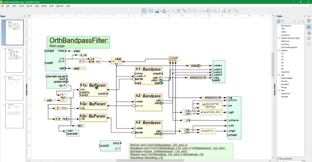
This video (8 min) explains a more comprehensive module or graphical model. It is the first video for that example and shows the approach how to deal really with graphical modelling.
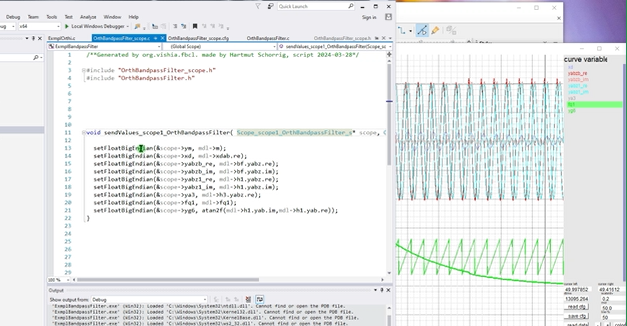
This video (13 min) shows how test results are output in a curve view, and how the functionality can be designed, tested and improved in the graphic module, with help of execution the generated code.
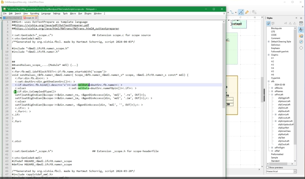
In this video (10 min) it is shown how the code generation for this specific scope program is done, with preparing of an ethernet telegram to the scope "Curve View" application, inclusively generation of the configuration of the code generation script
6.3. Details about running mode
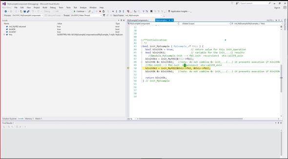
In this third video (6 min) it is shown in single step in the generated code how the initialization works. It is also the concept of emC for the phases constructor, initialization and run.
This video (8 min) enhances the example in the video above with the possibility to assign the aggregation between the classes in the constructor instead in the init…() routine. Both is possible.
Also the possibility of vice-versa aggregations are explained. But not full completely. The topic is, vise-versa aggregations in the constructor are not possible if allocated memory is used. Because the other instance does not exists if it is necessary for referencing in the constructor. That’s why aggregations can also be assigned in the init, after construction of all instances. This topic should be explained in an extra video, yet todo
7. Details to tools and handling
7.1. Approach and advantage of Zmake
See its main documentation on https://vishia.org/JZtxtcmd/html/Zmake.html
With the Zmake toolchain a shell script is generated and then called, which calls immediately the necessary compiler and linker commands with explicitly arguments. View this generated script shows the truth what is done on make, better than a make script with sophisticated dependencies and settings.
The second difference to familiar other make systems is: The decision whether a source file should be compiled or not does not only depends on its time stamp in comparison to the object file’s time stamp. It depends on content changes in the source files which are checked. This is essential for generated sources from graphic. Because: The sources are often newly generated from unchanged graphic content. Their content is the same, or almost the same, and it’s not necessary to compile. But the time stamp is new, and make does compile it.
A second reason using Zmake is: The decision whether a source file should be newly compiled should not only depend from the source file itself. It should depend also from all included files. For that the maker should know which files are included (over all) from any source file. That does often not work properly in make systems, so the user tends to a 'make all' approach. It is fatal, if a header file is substantial changed, and the maker does not recognize it. Make all is save, delete all objects, build all newly. It needs a little bit or a little bit more time.
Zmake detects all included header files, also in the depending tree
(header files includes also other header files), and checks the content.
This is done by the Java program org.vishia.checkDeps_C.CheckDeps
contained in the vishiaBase-20yy-mm-dd.jar.
If changes are detect, it deletes the given object file.
This is asked in the generated compilation script.
The compilation is avoided if the object file exists.
The object file is removed if the content of sources or included files are changed.
That is the simple truth and approach.
But how checks org.vishia.checkDeps_C.CheckDeps the content of the source files?
The simple kind without a copy of the 'older' version of the source files is: A check code is built. The check code, all dependencies and time stamps of all source and included files are contained in the file
build/COMPONENT/objZmake/COMPONENT/deps.txt
This file is built first time if not exists, and then of course all object files are removed,
or they are not existing as even the deps.txt. It is the initial 'build all'.
If this file exists, it is possible to compare the new detected check code of all source files,
store the new check code and remove the object file if necessary.
Included files are detected by its #include <path/file.h> syntax in the sources,
(also with quotation marks), combined with the include control file.
This file is also interesting by manual view to see what is all included.
src/COMPONENT/makescripts/cfgCheckDeps.cfg
which is used as argument of the org.vishia.checkDeps_C.CheckDeps java invocation.
On built of the check code of the sources comments are excluded. If only comment parts are changed, the source file is not detected as 'changed'. This is important if a generator of source files from graphic writes meta information in comment, or just if marginal information are changed such as graphic positions, which are contained in comments but have not influences to the target code.
The time to built these comparison information is significant lesser than the time for compilation. That helps save time for built.
7.1.1. Shell script execution in Windows used for Zmake
The Zmake approach needs to run shell scripts in Windows because the Zmake is written also for Linux, it is based on shell scripts. Using shell scripts in Windows is anyway a proper approach even for other situation. Instead, using also here batch files for Windows is double effort for writing and maintenance.
The MinGW, contained in Codeblocks, does support the GCC (Linux like) compilation, but unfortunately does not contain the ability of shell script execution. If Cygwin would be used instead of MinGW, which is also supported by Codeblocks for compilation, Cygwin contains shell script execution capability. It can be seen as the 'greater' but also more complicated solution instead MinGW (the "Minimalist GNU for Windows"). But the installation of Cygwin requests many options, have great capabilities and it is lesser proper especially for beginners.
Another way may be possible and is recommended: The Ability to execute shell scripts is given in a git installation (version management), which is often anyway sensible to use. If you are not familiar with git, you can copy a 'git portable' on your PC (without installation) first only for the shell script execution ability. Later you can use it also for your 'git' work. Look on
https://git-scm.com/install/windows - its official web page,
and download 'Git for Windows/x64 Portable.'.
You get a file PortableGit-2.53.0.2-64-bit.7z.exe (current version seen on 2026-04-11) or a newer version
with ~ 60 Mbyte size. It is a zip archive with self unpacking capability.
If you execute it, it asks for the destination directory.
I have selected C:\Programs\Git-Portable-2.53 as destination for this version.
And now, it’s complete. Both, the execution of shell scripts and the GCC compiler suite is given. The last one with using the MinGW part in the Codeblocks IDE, see chapter Codeblocks as IDE-tool - the possible beginners approach. The execution of shell scripts is organized with the batch file
~~/src/scripts/WindowsEnv/shell.bat
contained in the download. You can adapt your paths for the both components, if the installation folder or versions are a little bit other. See content of the simple script, edit it. The yet default setting is:
 C:\Programs\Git-Portable-2.53
 C:\Programs\Codeblocks\2020\MinGW\bin
7.1.2. Call of Zmake
For generation of the shell script to compile and link the so named JzTxtCmd tool chain is used. This is described in
This tool is contained as also checkDeps in the vishiaBase-20yy-mm-dd.jar.
It is invoked with the main class org.vishia.jztxtcmd.JZtxtcmd.
This java call is contained in the user specific first level script,
src/COMPONENT/makeScripts/TARGET.Zmake.jzTc.sh
After some small preparations. After call the script file generator JzTxtCmd the generated file is called in this shell script:
../build/$CMPN/make_$CMPN.sh
This generated compilation shell script can be visited and even be called also manually, for example to search non obviously compilation errors. The compilation shell script writes all outputs of compilation and linking in text files:
build/COMPONENT/result/COMPONENT.cc_err
7.1.3. File sets and options for Zmake
The files used for compilation and some compiler options are all determined by the content of the file
src/COMPONENT/makeScripts/filesets.jzTc
This file is included in the JzTxtCmd translation and contains data definition:
String inclPath =  ##from position of the generated make.cmd file
<:> <: >
-Isrc/src_emC/cpp/emC_inclComplSpec/cc_Gcc64 <: >
-Isrc/ExmplPositionCtrlPID/cpp <: >
-Isrc/src_emC/cpp<.>;
This is a simple variable definition with its content between <:>…<.>.
It contains the original used String for arguments of the include path.
Adequates it is given for the
String libs =
<:><: >
-lpthread <: >
-lwsock32<: >  ## Note: MinGW on Codeblocks supports WinSock, not the BSD Sockets
<.>;
Note: The <: > ignores all white spaces after it, and allows writing more lines
which is accomplished to the simple string, here "-lpthread -lwsock32"
Fileset src_OSALgcc =
( src/src_emC/cpp:emC/OSAL/Environment_OSALemC.c
, src/src_emC/cpp:emC_srcOSALspec/os_LinuxGcc/os_environment.c
##, src/src_emC/cpp:emC_srcOSALspec/hw_Intel_x86_Gcc/os_atomic.c
##, src/src_emC/cpp:emC_srcOSALspec/os_LinuxGcc/os_endian.c
, src/src_emC/cpp:emC_srcOSALspec/os_LinuxGcc/os_thread.c
, src/src_emC/cpp:emC_srcOSALspec/os_LinuxGcc/os_error.c
##, src/src_emC/cpp:emC_srcOSALspec/os_LinuxGcc/os_file.c
, src/src_emC/cpp:emC_srcOSALspec/os_LinuxGcc/os_mem.c
, src/src_emC/cpp:emC_srcOSALspec/os_LinuxGcc/os_time.c
, src/src_emC/cpp:emC_srcOSALspec/osal_Windows/os_socket.c ## Note: MinGW on Codeblocks supports WinSock, not the BSD Sockets
);
A Fileset builds a container variable containing elements with the given Strings.
The ## is the comment symbol, it means this lines (or files) are deactivated.
So used files can be selected in a simple way.
For this example that are the OSAL files (Operation System Adaption Layer).
Whereby it is interesting that the MinGW compiler in Codeblocks uses the POSIX pthread approach,
but not the POSIX (BSD or Berkeley) sockets as in UNIX, instead uses the Windows socket hardware driver.
There are more file sets, sorted to comprehensive components. The last, used fileset for this example is:
Fileset src_ExmplPositionCtrlPID =
( &c_src_emC_core
, &src_OSALgcc
, &src_Ctrl_emC
, src/ExmplPositionCtrlPID/cpp/genSrc:ExmplPositionCtrlPID_F.c
, src/ExmplPositionCtrlPID/cpp/genSrc:ExmplPositionCtrlPID_I.c
, src/ExmplPositionCtrlPID/cpp/genSrc:ExmplPositionCtrlPID_S.c
, src/ExmplPositionCtrlPID/cpp/genSrc:SimpleExmplCtrlPID.c
, src/ExmplPositionCtrlPID/cpp/genSrc:TestF_DT1.c
, src/ExmplPositionCtrlPID/cpp/genSrc:TestF_DT1_scope.c
, src/ExmplPositionCtrlPID/cpp/genSrc:TestPositionCtrlPID.c
, src/ExmplPositionCtrlPID/cpp/genSrc:TestPositionCtrlPIDint.c
, src/ExmplPositionCtrlPID/cpp/genSrc:TestPositionCtrlPIDint16.c
, src/ExmplPositionCtrlPID/cpp/genSrc:TestPositionCtrlPIDall.c
, src/ExmplPositionCtrlPID/cpp/genSrc:TestPositionCtrlPIDall_scope.c

, src/ExmplPositionCtrlPID/cpp/testEnv:main_ExmplPositionCtrlPID.c
, src/ExmplPositionCtrlPID/cpp/testEnv:test_ExmplPositionCtrlPID.c
, src/ExmplPositionCtrlPID/cpp/testEnv:test_Ts_Exp.c
);
This is for the example.
The files in genSrc are the generated ones from the LibreOffice Draw graphic genScr_odg.bat.
This file set is offered in the start JzTxtCmd script src/COMPONENT/makeScripts/TARGET.Zmake.jzTc.sh
in the JzTxtCmd main operation
main() {
  ##Generate all relevant test cases
  ##debug;
  call build_dbgC1(CMPN="ExmplPositionCtrlPID", testCase="ExmplPositionCtrlPID", defines = "", srcSet = src_ExmplPositionCtrlPID, ccSet=ccSetDeflt ); ##srcset_Basics); ##
}
which is the JzTxtCmd main entry.
7.1.4. Generation script for Zmake
The generation script is included in the start JzTxtCmd script src/COMPONENT/makeScripts/TARGET.Zmake.jzTc.sh via
==JZtxtcmd==
include ../../scripts/Zmake/genScriptZmake_emC.jztc;  ## The JzTxtCmd script to generate the compile shell script
include filesets.jzTc;                                ## The relevant files for this target.exe

main() ##....
The general script in src/scripts/Zmake/genScriptZmake_emC.jztc contains the generation rules
for the shell script to generate for compilation and linking.
It contains the build_dbgC1 sub routine in JzTxtCmd syntax, or if necessary
also some other routines:
##
##Generates the files for compile and test (shell script)
##
sub build_dbgC1 ( String CMPN, String testCase
    , List defines
    , Obj ccSet      ##Variables which determines the compilation, setting
    , Obj srcSet) {

  <+out>Generates: build/make_test_emC.sh for compilation and start test ...
  ....
JzTxtCmd is a combination of script execution, whereas Java operations are invoked via Reflection mechanism, and text output generation. In the script example above an textual output is written to the stdout (console).
The text generation is controlled via (example)
  String sMake = <:>build/<&CMPN>/make_<&testCase>.sh<.>;
  <+out>Generates: <&sMake><.+n>
  Openfile makesh = sMake;
  <+makesh># call of compile, link and execute in the make_....sh script
    <:>
====echo ----------------------------------------------
====echo -
====echo called: $0
====echo working dir to compile should be the SOURCE.wrk where ./src and ./build are found.
====cd $(dirname "$0")/../..
====pwd                                                                          ##first invoke checkDeps
====echo ----------------------------------------------
====echo -
====. src/scripts/LinuxEnv/SetJCP.sh  <:##> sets the $JCPVISHIA
====if ! test -d build/<&CMPN>/result; then mkdir -p build/<&CMPN>/result; fi
    ....
    <.><.+>
This is the creation of the first lines of the generated make…sh script.
Texts are outputed between <:> and <.> as written.
Variable values are inserted via syntax <&CMPN> here for the variable CMPN.
Outside of <:>…<.> variables and statements are written in JzTxtCmd syntax,
which is readable and similar other languages.
7.2. Hints Handling load, file tree
Also handling with "load tools"
Hint for the file tree in the examples: The generally approaches for the file tree are described in ../../SwEng/html/srcFileTree.html.
It means here:
Working_tree_where_zip_is_unpacked
 +-tools           This is created after src/load_tools
 +-IDE             This is created after executing a +spawn_IDE_....bat
 |  +-Example_Component
 |     +-CB        for Codeblocks projects to execute and test
 |     +-MSC       for Visual Studio projects to execute and test
 +-src             The sources, only this directory is contained in the zip
    +-load_toos    To load the translation tools for UFBgl from vishia page
    +-src_emC      Version of used sources from emC (embedded multiplatform {cp})
    +-Templates_odg contains the odg template file, and makescripts to create onw stuff
    +-Example_Component
    |  +-IDE...        The IDE files to spawn it.
    |  +-+spawn_IDE_....bat click it to spawn
    |  +-odg           Here is the odg file for this example
    |  +-cpp           Some {cp} files
    |  |  +-genSrc     This are the destination for generated {cp}-Files
    |  +-cmpGen        This directory contains the versions from older generations, to compare
    |  +-curveView     Files for the CurveView toool
    |  +-makeScripts   Files to translate the module.
    +-ExmplBandpass    It is such an example
       +-IDE
       +-odg           ... etc.
7.2.1. Where to store generated sources, JUNCTIONs or symbolic linked directories
There is a decision where to create the folder for the generated sources. I see three possibilities which advantages and disadvantages:
-
a) Do not create this JUNCTIONs or linked folders, write the sources immediately in
~~/src//<EXAMPLE>/cpp/genSrc.Disadvantage: It is immediately a part of the sources in the
src/treethough it is generated. Any new generation writes on SSD or the hard disk. -
b) Write the generated sources outside the source tree to
~~/build/<EXAMPLE>/cpp/genSrcAdvantage: The generated sources are outside of the primary sources. This will be done in fact because a symbolic link or JUNCTION in MS-Windows is created from⇒to~~\build => %TMP%\OFB_presentation\
and hence the sources are seen also there.
Disadvantage: Taking the sources from~~/build/…in a IDE project is a little bit more confusing. It is better, sources are beside together. (Is it a disadvantage). -
c) Write the generated sources to
~~/build/…but without symbolic links or JUNCTIONs:Hm, symbolic links are a proper possibility well known in UNIX from the 1970th
(ln -s /path/to/dst linkname), should be well known in Linux,
and introduced in the Windows-world first with Windows-Vista ~2008, but only for the NTFS file system.
But for some people they may be confusing.
Have experience and fun.
7.3. Write results to build, optimising access to the hard disk, RAMdisk and symbolic links
General, sources are stored in ~~/src, results, also the generated target (second-) sources
should not be merged with the first intrinsic sources.
That’s why the destination for all translating is ~~/build.
More exact, the scripts uses an environment variable BUILDD which is preset to ..\..\build as relative path from the component’s directory.
For practical approaches, this build directory can often be a symbolic link which refers either to a RAM disk or to a destination in a network,
on another computer, where immediately the generated secondary target secondary sources
This is not a topic of the OFB approach and tools, but it is recommended (also here) to think above:
RAM disk
If you have a lot of temporary files, writing all these on your hard disk needs a little bit time, even if only milli- or microseconds per file. But the more important problem is: Frequently writing on hard disk puts strain on it, more for SSD as for magnetic disks. On the other side, RAM is usual enough in your system. If you have 16 GByte RAM, and you spend only 1..2 GByte as RAM disk, it is enough for all temporaries. The translation is faster and your Hard disk is spared. This is true for the generated target source files, as also especially for Object, Map and executable which are usual used only for a short test. Of course proven files should then be copied to a permanent storage.
Symbolic links (Unix, Linux) or JUNCTION in MS-Windows
To work with the RAM disk, and also using relative paths recommended, symbolic links helps to work.
Symbolic Links are familiar in UNIX since beginning (1970th). In DOS till Windows XP there are not available.
Only beginning with Windosw-7 for the NTFS file system so named JUNCTIONS are usable with similar capabilities as symbolic links in UNIX.
This symbolic links allows to write the generated sources in a build directory beside and separated from the sources in src.
But the files can be really stored on the RAM disk, or on another proper location, also in the network.
I use partially the RAM disk of another PC to store the files, because the other PC is used to compile the target project.
This does not save time, because the files should be transferred via Ethernet to the RAM disk, But is spares the hard disk.
In an adequate way the yet currently generated target source files can be used in a project for target software generation which can be located not only on another main directory path on the same computer, but also on another computer connected in the network. Symbolic links or JUNCTION on MS-Windows in combination with substituted network drives can be used to interact between the sources.
For the examples the destination of target code generation is always the
~~/build/<COMPONENT>/genSrc
The build directory is symbolic lined to the temporary directory:
%TMP%\OFB_presentation\build\<COMPONENT>\genSrc
It means the generated sources are stored in the temp folder of your computer.
It is temporary, can be deleted again after the session.
I use (recommended) a RAM disk for the whole MS-Windows temporary stuff, that works.
The computer is faster and the SSD is spared.
But in some scripts after making any JUNCTION a pause is programmed, you need to "press any key to continue"
If JUNCTION on MS-Windows does not work because you have not an NTFS file system, then the build directory is created
where it is located on the hard disk, or for example on an USB-stick which is even not NTFS-formatted. It works anytime.
As you see, some small problems are in the source, especially ExmplWaveAvg is not yet ready.
But the videos are made with this version.